
These days, everything depends on electricity. We use electricity all the time but give little thought to how electricity makes it to our bedsides, sofas, and kitchens. Transformers facilitate electricity’s journey from power station to plug sockets in our home. This article, a part of our series on magnetism and electromagnetism, explains how electricity becomes useful and safe for household and industrial use.
Transformer Physics and Functions:
- Transformers have a primary coil and a secondary coil.
- Step-up transformers have fewer turns on their primary coil than the secondary coil.
- Step-down transformers have more turns on their primary coil than the secondary coil.
- Transformers rely on electromagnetic induction to create a safe, usable electrical supply.


Transformer Physics: Fundamental Transformer Principles
Most people have a vague idea of what transformers do. You might have gotten a better idea from our introduction. But that bit of information still doesn't tell you much about transformer efficiency, nor does it provide any example you could relate to. Now's the time to deliver that information.
Faraday's Law and Electromagnetism
Physicist Michael Faraday developed a fascination with electricity and its potential. He was a young man when early experiments in the science of electromagnetism began gaining widespread recognition in the 1820s. He set his keen mind to exploring the subject.
Through his experiments, he found that moving a magnet close to a coiled wire induced a small voltage. Likewise, moving the magnet away caused a small deflection in the galvanometer's needle. In short, he concluded that any change in a magnetic field resulted in an electromotive force (EMF) in a coil. From those observations, he formulated his Law1.
Any change in the magnetic environment of a coil of wire will cause a voltage (EMF) to be "induced" in the coil.
Electromagnetism is the combination of electric current and magnetism. Transformers work by exploiting this relationship. In fact, they are a representation of Faraday's Law at work2.
Transformer Construction
Transformers consist of two or more coils of wire around a ferromagnetic core.
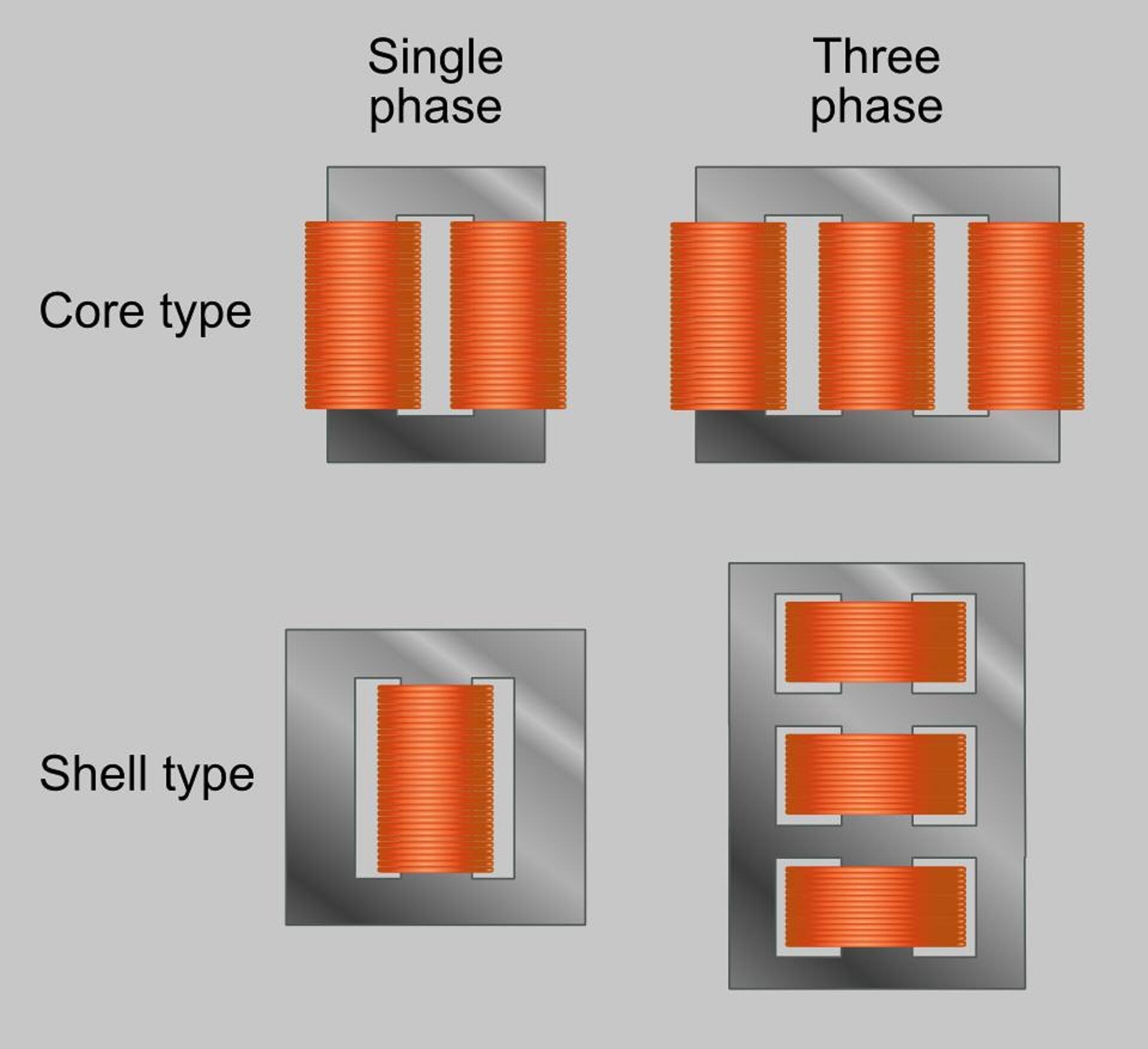
It helps to picture a square of iron with two windings of copper wire opposite one another, as seen in the upper-left corner. When voltage is applied to the primary coil, it creates magnetic flux which passes through empty space to the secondary coil. In other words, it induces a current in the secondary coil.
This is how a standard transformer works: exercising what we call electromagnetic induction.
The Importance of Alternating Current (AC)
Transformers only work with AC applied. This type of current fluctuates, constantly reversing direction. Without variability in the transformer's magnetic field, there could be no transfer of electricity.
DC current flows always in the same direction.
AC produces the change to the magnetic flux that permits the transfer of electrical current.
In other words, AC permits the induction of electricity in the secondary wire. DC does not.
Transformer Turns Ratio and Voltage Relationship
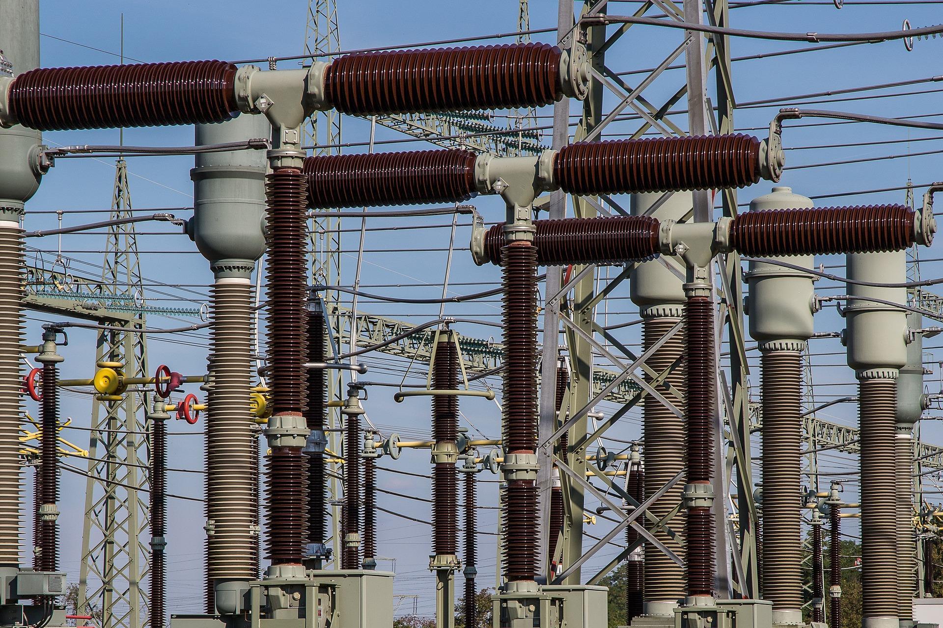
Transformers allow the transfer of power from a high-voltage circuit to one of lower voltage or medium voltage. Or from a low-voltage circuit to a higher-voltage one. We find these devices throughout every power system, from microcircuits to massive industrial applications3. As such, we must understand how they manage their function across a range of applications.
The Relationship Between Voltage and Turns Ratio
As noted above, DC current wouldn't induce electromagnetic force thanks to its same-direction current flow. Likewise, a transformer with the same number of turns on each coil (winding) would not change the voltage from one coil to the next. So, we see a relationship between each winding's voltage and the number of turns it has:
The voltage ratio between a transformer's primary and secondary windings is directly proportional to the turns ratio.
V1 / V2 = N1 / N2 - where
V1, 2 = primary and secondary voltage
N1, 2 = primary and secondary number of turns
This straightforward formula tells us that if the primary winding has more turns than the secondary, the voltage 'steps down'. Likewise, if the secondary winding has more turns, the transformer is a step-up type.
Current and Power in Transformers
In this respect, transformers also present an inverse relationship. Ideally, transformers maintain equal power output across their windings5. We can express this with a mathematical formula, too.
Pp = Ps where
P = power
However, we find an inverse in the relationship between voltage and current.
Step down transformer
- the primary winding has more turns
- lower voltage than the secondary winding
- higher current than the secondary winding
Step up transformer
- the secondary winding has more turns
- higher voltage than the primary winding
- lower current than the primary winding
These are fundamental concepts that every student masters in their earliest physics courses. With this refresher applied to transformers, we can look at different types of transformers and their uses.
Types of Transformers And Their Uses
Transformers' purpose and function is universal but not all transformers are the same. Above, we briefly compared two types: step up vs step down transformer. Now, we take a closer look at how they work and what they're used for, along with a few other types of transformers.
Step-Up vs. Step-Down Transformer
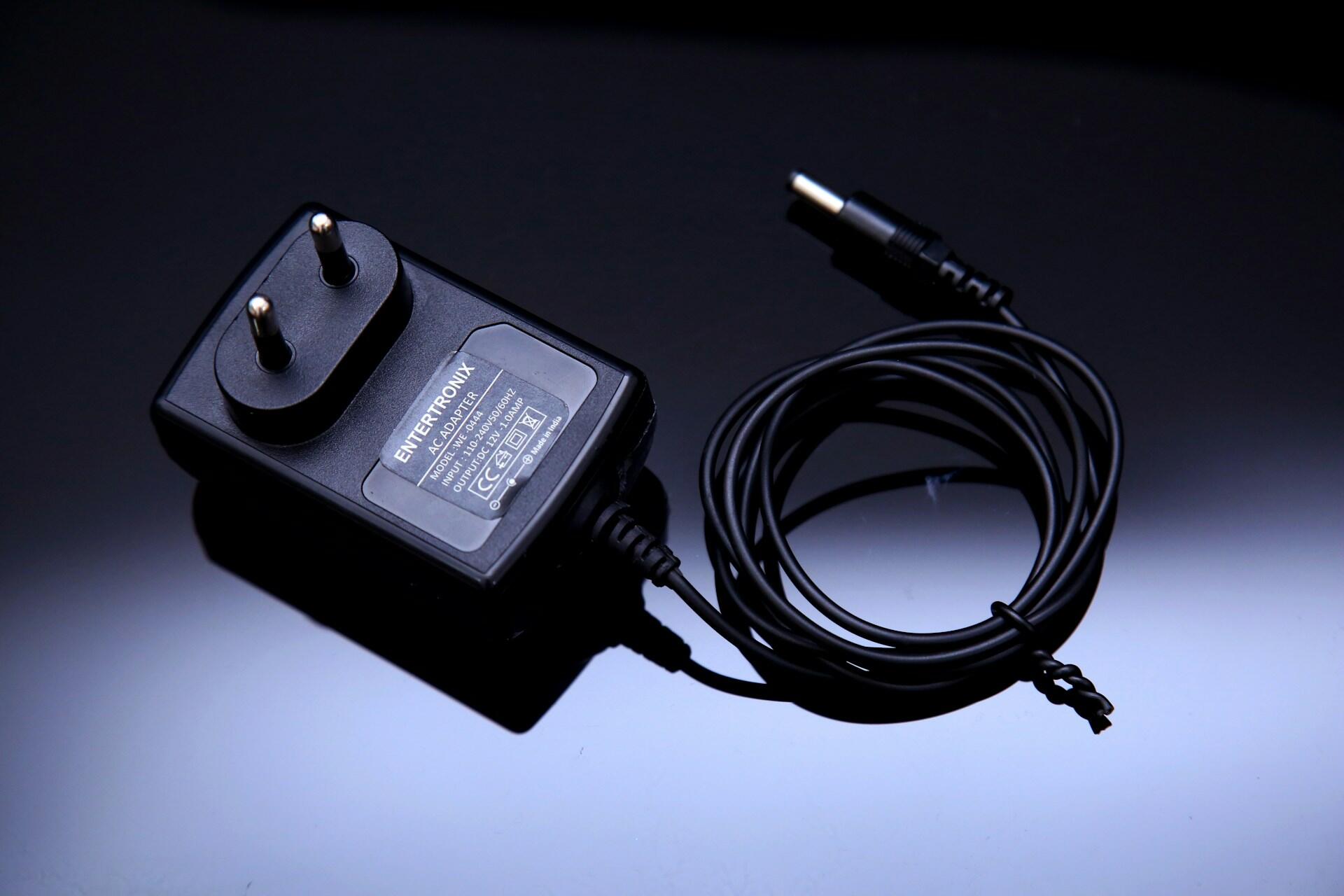
Did you know your electronic device chargers were step-down transformers? They accept the relatively high household voltage and convert it to a voltage acceptable to sensitive electronic components.
You may also be familiar with step-up transformers, particularly if you have any experience with wind or solar power. These devices' relatively low-voltage collection need a boost to integrate with standard electrical grids, to make it usable.
The step-up vs. step-down transformer, along with isolation transformers, are the three main transformer types across electrical and electronic applications.
Step-up transformers increase the voltage from the primary to the secondary windings. Step-down devices do the inverse: they decrease voltage from primary to secondary windings. These transformers have uses in virtually every electrical application, from distributing energy long-distance (step-up) to making sure every household gets its fair share (step-down).
Isolation Transformers
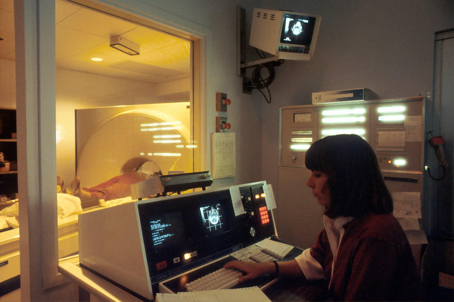
Isolation transformers are the third main type of transformer. Just as their names suggest, these devices maintain their voltage while ensuring electrical isolation. These types of transformers are used in medical equipment such as MRI machines, and other applications where safety is a paramount consideration.
Primary and secondary windings have the same number of turns.
These devices do not change voltage output, like the step transformers do. Rather, they insulate the machine from external voltage. Thus its electrical output is pure induction; these transformers have no electrical connections between primary and secondary windings. This feature cancels noise transfer between the windings.
Autotransformers
These are singular devices in more ways than one. They have only one winding, and a movable contact which varies the output voltage. Adjusting the contact's setting changes which part of the winding is in the circuit, allowing users to smoothly change the voltage of the circuit it's embedded in.
Though similar in function, a rheostat - a 'dimmer switch' that changes the lighting in your home is not the same as an autotransformer.
Now that the dimmer switch debate is clear, you can look for autotransformers in modern vehicles to regulate motor speed. Otherwise, they are mostly found in laboratories and equipment testing facilities. Ask your Physics tutor for more autotransfer examples and if they've had occasion to use them.
Transformer Examples in Daily Life
We've given examples of transformer usage in common household applications; now let's broaden our scope.
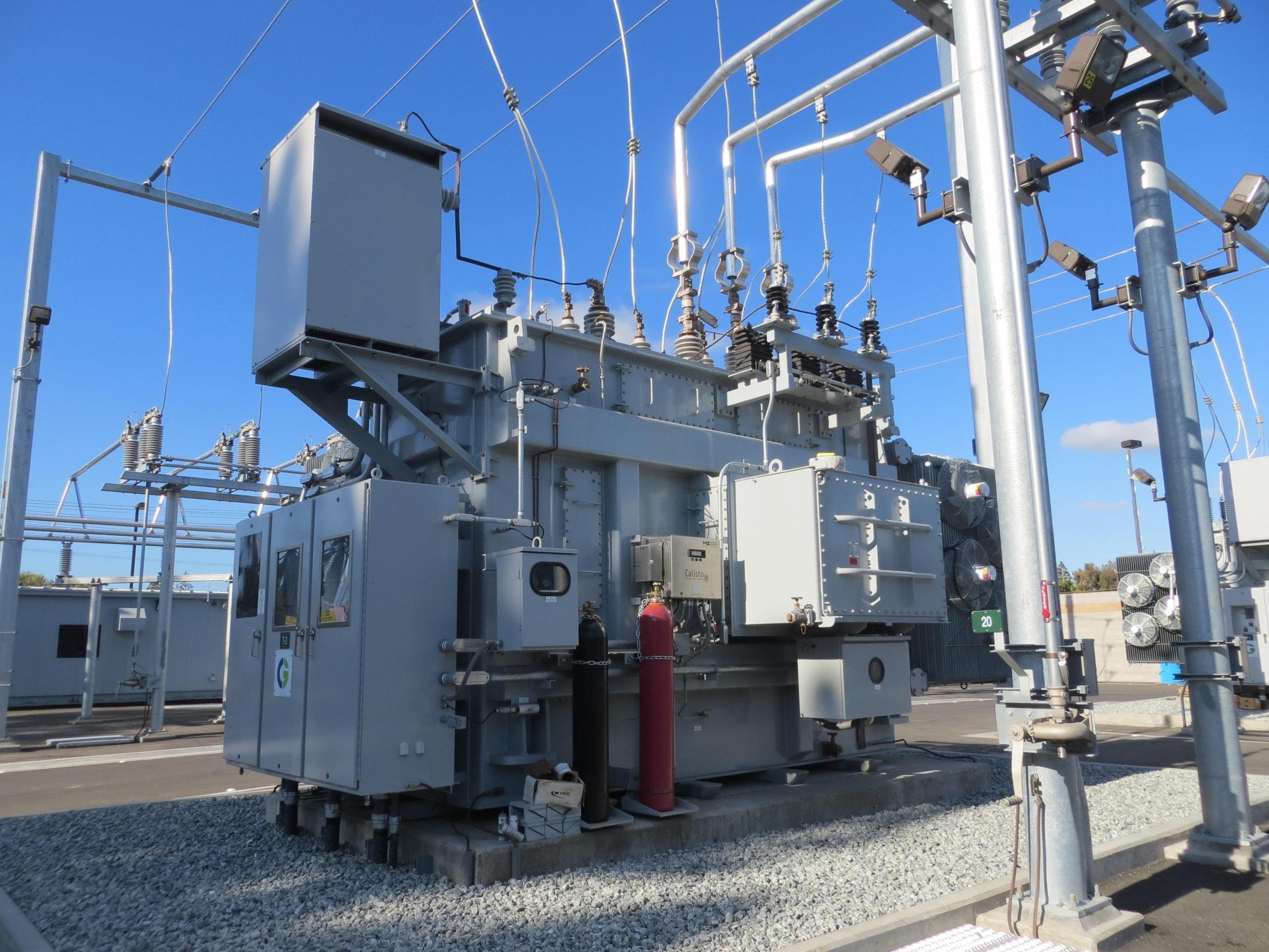
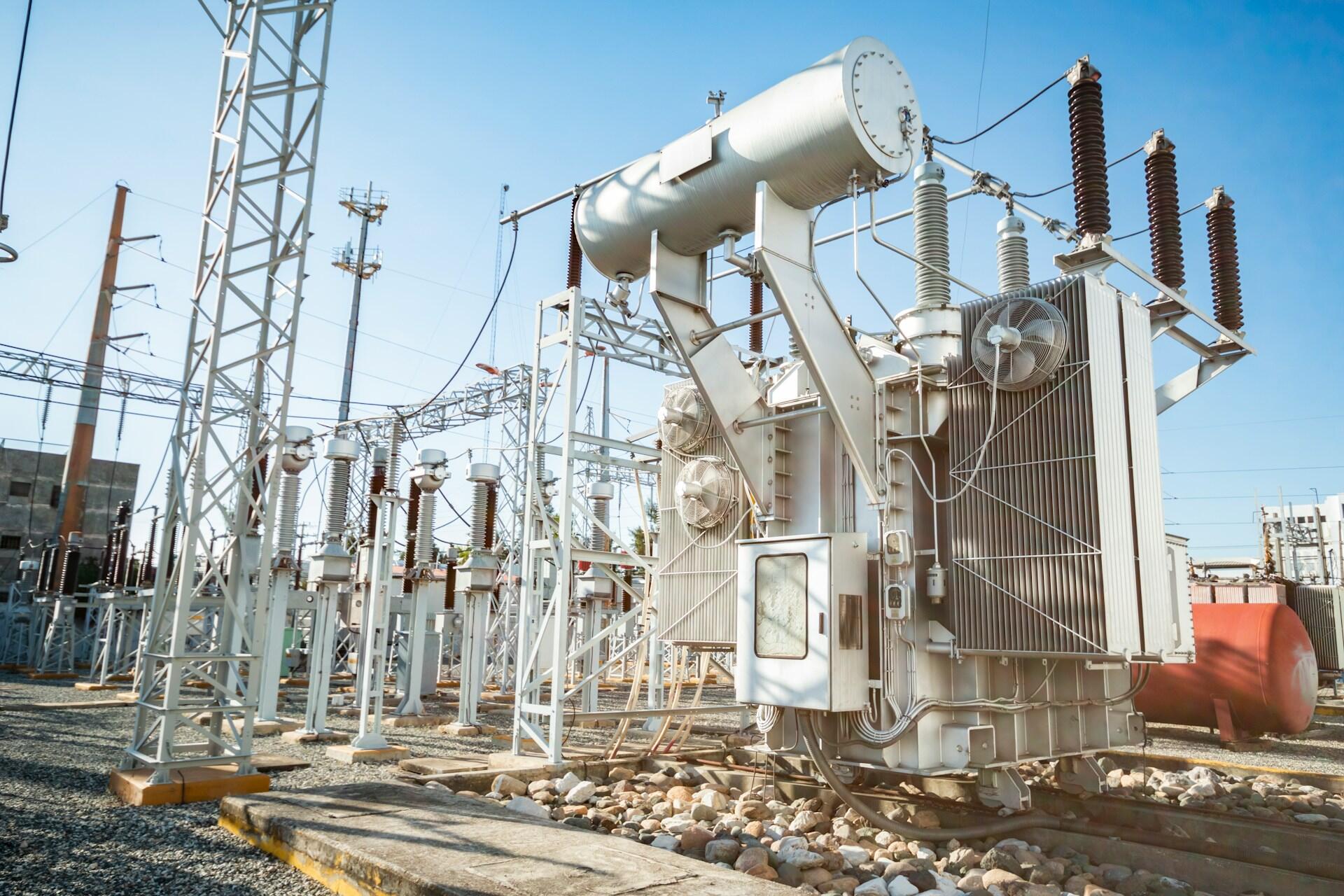
Transformer Efficiency in Power Distribution
All electrical power passes through at least one transformer between its generation and delivery points. Typically, that entails travelling long distances, risking substantial voltage drop along the way.
The tendency to lose electrical potential along the path of current flow.
Electrical production stations typically have step-up transformers at their output stations to boost the voltage as high as possible as it heads out of the facility. Transformers are installed along the path to break up the circuit into smaller parts and to ensure a consistent voltage flow. This allows greater stability in the transmission and makes it easier to isolate issues.
Transformers in Electronic Devices
At the opposite end of mega-watt electrical distribution lies the delicate microcircuitry in electronic devices. You already know that your neighbourhood transformers step voltage down to make it suitable for safe household usage. And, earlier you read that your electronic devices have step-down transformers built into their charging cables.
But the delicate circuitry inside your devices demand yet more voltage/current regulation. As any Physics tutor could tell you, printed circuit boards (PCBs) also have transformers on them for that purpose. They are typically air core transformers; they look like copper-clad donuts.
Transformers Further Reading and Resources
- Prof. R. Nave: http://hyperphysics.phy-astr.gsu.edu/hbase/electric/farlaw.html
- Chris Woodford: https://www.explainthatstuff.com/transformers.html
- Richard Nailen: https://web.archive.org/web/20090429031651/http:/www.blnz.com/news/2008/04/23/must_concerned_with_transformers_9639.html
- Electrical Academia: https://electricalacademia.com/transformer/transformation-ratio-of-transformer/
- Electronics Tutorials: https://www.electronics-tutorials.ws/transformer/transformer-basics.html
- Sourav Gupta: https://circuitdigest.com/tutorial/different-types-of-transformers-and-their-applications
Summarise with AI:
Did you like this article? Leave a rating!


